Chapter 1: System Components
Architecture boundaries, component inventory, working principles, and engineering KPIs for all cabling system elements.
1.1 System Architecture and Boundaries
The video surveillance cabling system is structured around a clear deployment boundary: from the camera tail connector at the endpoint, through horizontal copper cabling, zone access cabinets, fiber backbone trunks, to the headend patch panel in the equipment room. Understanding this boundary is critical for scope management, responsibility assignment, and systematic troubleshooting.
The system is divided into three tiers of components: Core components that are mandatory for every deployment, Optional components that enhance resilience or functionality, and Supporting components that provide the operational environment. Each tier has distinct engineering requirements and acceptance criteria.
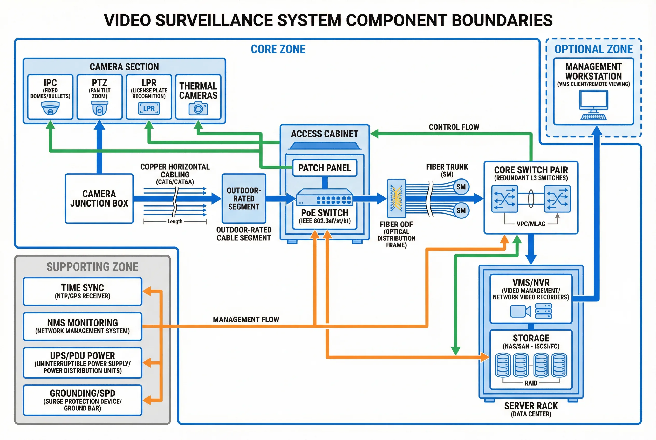
Figure 1.1: System Component Block Diagram — Core, optional, and supporting zones with data flow (blue), control flow (green), and management flow (orange) arrows.
Deployment Boundary: This guide covers from camera tail to headend patch panel, including cabinets and pathways, and design interfaces to UPS, grounding, and physical security systems. Civil construction beyond cable pathway provisions and VMS software configuration are out of scope.
Component Classification
- Core (mandatory): Camera drops, horizontal cabling, access PoE switching, backbone fiber, headend patching, labeling/testing, grounding/surge points.
- Optional (enhancing): Redundant access switching, dual-homing cameras (rare), wireless bridges for special cases, edge recording SD cards, environmental sensors in cabinets.
- Supporting (operational): UPS, distribution boards, fire-stopping, cooling/ventilation, physical security (locks, access control), network monitoring systems.
1.2 Components and Functions
Each component in the cabling system has a defined responsibility, specific inputs and outputs, measurable KPIs, and known mismatch risks when incorrectly specified or installed. The diagram and table below provide a comprehensive inventory of all components with their engineering parameters.
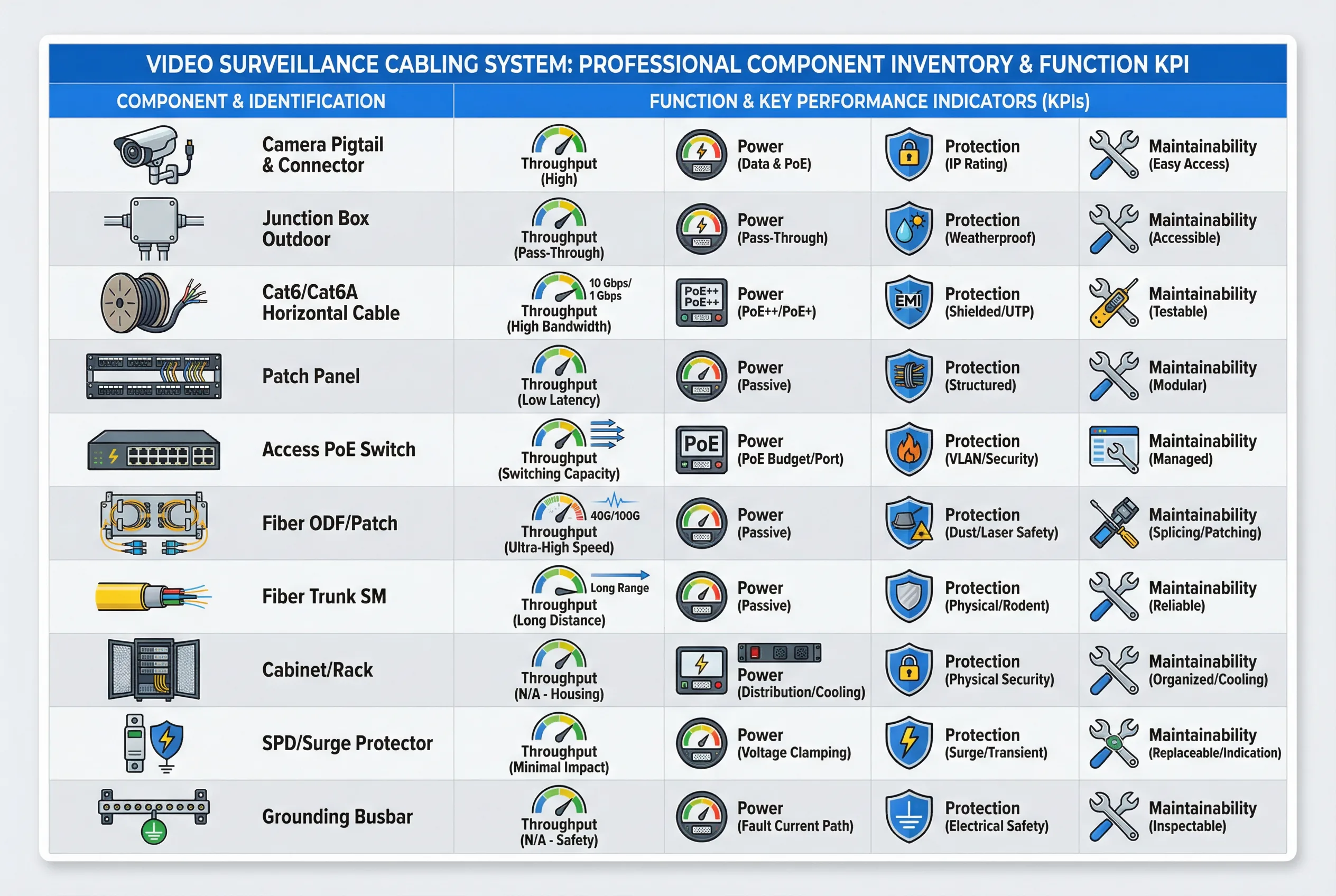
Figure 1.2: Component Inventory and KPI Overview — Each component mapped to throughput, power, protection, and maintainability dimensions.
| Component | Responsibility | Inputs | Outputs | Key KPIs | Mismatch Risks |
|---|---|---|---|---|---|
| Camera pigtail & connector | Reliable endpoint termination | PoE power, Ethernet | Video stream | IP rating, strain relief | Water ingress, intermittent link |
| Junction box (outdoor) | Seal + service point | Cable in/out | Protected splice/termination | IP66/67, gasket quality | Condensation, corrosion |
| Cat6/Cat6A horizontal | Data + PoE transport | Ethernet signal | Ethernet signal | Insertion loss, NEXT, DC resistance | Frame drops, PoE brownout |
| Patch panels | Structured termination | Permanent link | Patchable ports | Label clarity, port density | Mispatch, wrong camera mapping |
| Access PoE switch | Power + switching | AC/UPS, uplink | PoE ports, uplink | PoE budget, thermal, uptime | Random reboot, port flaps |
| Fiber ODF/patch | Backbone termination | Fiber trunk | Patchable fibers | Loss (dB), cleanliness | High loss, intermittent errors |
| Fiber trunk (SM) | Long-distance, EMI immunity | Optical signal | Optical signal | Attenuation, splice loss | Link down, CRC errors |
| Cabinet/rack | Protection + organization | Devices/cables | Structured layout | Ventilation, ingress rating | Overheat, physical damage |
| SPD/surge protector | Surge diversion | Lightning transient | Reduced surge energy | Clamping voltage, response time | Equipment damage from surge |
| Grounding busbar | Equipotential bonding | Earth reference | Bonded system | Continuity (Ω), corrosion resistance | Noise, surge vulnerability |
1.3 Working Principles
Startup Sequence
- Verify cabinet power: AC → UPS → PDU stable; check earth continuity before energizing.
- Power up access switches; verify PoE budget headroom against planned camera load.
- Link-up camera ports; verify negotiated speed and duplex (1G full expected).
- Confirm camera IP assignment (DHCP reservation or static per IP plan).
- VMS discovers cameras; verify stream profiles, bitrate, and time synchronization.
Normal Operation
During normal operation, cameras continuously push RTP/RTSP/ONVIF streams to VMS/NVR while the VMS sends control commands (PTZ, configuration) back through the same network path. The NMS monitors port errors, PoE draw, temperature, and fiber light levels. Storage writes sustained throughput while headend uplinks remain below the design utilization threshold.
Abnormal Chains and Recovery
| Abnormal Event | Symptom | Root Cause Chain | Recovery Action |
|---|---|---|---|
| PoE brownout | Camera reboots at night | IR heaters activate → PoE draw exceeds budget → port cycling | Redistribute cameras, upgrade switch PoE budget, add headroom |
| Moisture ingress | Intermittent link drops | Poor outdoor seal → condensation → corrosion → contact resistance | Replace junction box, re-terminate with IP-rated components |
| EMI interference | CRC errors on copper | Cable near VFD/motor → induced noise → frame errors → retransmit | Reroute cable, add separation, consider fiber in EMI zones |
| Fiber uplink cut | Zone cabinet offline | Physical damage → link down → cameras offline → recording gap | Activate redundant uplink B, repair fiber, verify convergence |
| Cabinet overheat | Switch reboots intermittently | Blocked vents → thermal throttling → switch restart → multiple cameras offline | Add ventilation, derate PoE density, relocate heat sources |