Chapter 5: Selection & Interfaces
Core product selection criteria, interface specifications, wiring standards, and functional comparison tables for surveillance cabling components.
5.1 Core Product Overview
The surveillance cabling system relies on a carefully selected set of core products, each with specific performance requirements that directly impact system reliability and video quality. The table below presents the primary product categories, their key specifications, and selection criteria. Choosing products that exceed minimum requirements provides headroom for future upgrades and reduces the risk of performance bottlenecks as camera resolutions and frame rates increase.
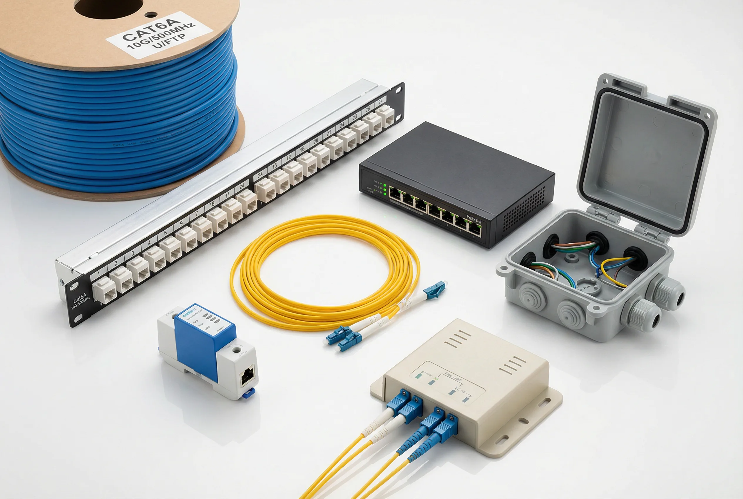
Figure 5.1: Core Products for IP Video Surveillance Structured Cabling Systems
| Product | Category | Key Specifications | Selection Criteria | Typical Use |
|---|---|---|---|---|
| Cat6A U/FTP Cable | Copper Horizontal | 10G, 500 MHz, 4-pair, 23 AWG | LSZH or PVC jacket; plenum if required | Camera drops ≤90 m |
| Cat6A Patch Panel | Copper Termination | 24/48-port, T568B, 1U/2U | Toolless or 110-punch; labeled ports | Zone cabinet termination |
| Cat6A Patch Cord | Copper Connection | Snagless boot, ≤5 m, pre-tested | Color-coded by zone or function | Panel-to-switch connection |
| OS2 Single-Mode Fiber | Fiber Backbone | 9/125 µm, G.652D, LSZH | Armored for outdoor/buried runs | Inter-building backbone |
| OM4 Multimode Fiber | Fiber Backbone | 50/125 µm, 4700 MHz·km, LSZH | For intra-building runs <300 m | Intra-building backbone |
| LC-LC Fiber Patch Cord | Fiber Connection | OS2 yellow / OM4 aqua, ≤3 m | Factory-polished, insertion loss <0.3 dB | ODF to switch SFP |
| 24-Port Fiber ODF | Fiber Termination | LC/SC adapters, 1U, sliding tray | Sliding tray for easy access | Zone cabinet fiber termination |
| PoE+ Switch (802.3at) | Active Network | 24/48-port, 30W/port, 370/740W total | Managed, VLAN, QoS, SNMP | Standard IP cameras |
| PoE++ Switch (802.3bt) | Active Network | 24-port, 90W/port, 1440W total | For PTZ, multi-sensor, heated cameras | High-power camera applications |
| IP66 Junction Box | Outdoor Enclosure | IP66/67, UV-resistant, cable glands | Stainless steel or polycarbonate | Outdoor camera termination |
| RJ45 SPD | Surge Protection | Data + PoE protection, <1 ns response | DIN rail or inline mounting | Outdoor cable building entry |
| Zone Cabinet (Wall) | Enclosure | 9U–15U, lockable, ventilated | IP30 minimum; IP54 for harsh areas | Zone distribution point |
5.2 Interface Specifications and Wiring Standards
Correct interface termination is fundamental to achieving certified channel performance. The T568B wiring standard is the most common in surveillance deployments and must be applied consistently at both ends of every horizontal run. Mixing T568A and T568B within the same channel creates a wiring fault that will cause link failure. All fiber connectors must be cleaned before mating and tested with an optical power meter to verify insertion loss within specification.
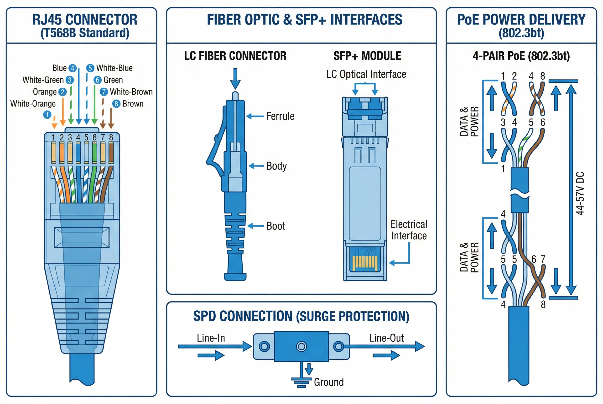
Figure 5.2: Interface Specifications — RJ45 T568B Wiring, Fiber Connectors, PoE Power Delivery, and SPD Connection
| Interface Type | Standard | Key Parameter | Test Method | Pass Criterion |
|---|---|---|---|---|
| RJ45 (Cat6A) | T568B / TIA-568.2-D | Insertion loss, NEXT, return loss | Fluke DSX-8000 or equivalent | Category 6A channel PASS |
| LC Fiber (OS2) | IEC 61754-20 | Insertion loss <0.3 dB/connector | OTDR + optical power meter | End-to-end loss <3 dB |
| SC Fiber (OS2) | IEC 61754-4 | Insertion loss <0.3 dB/connector | OTDR + optical power meter | End-to-end loss <3 dB |
| SFP+ (10G) | IEEE 802.3ae | Tx power, Rx sensitivity | Optical power meter at Rx | Within module spec range |
| PoE (802.3at/bt) | IEEE 802.3at/bt | PSE output: 44–57V DC | PoE tester or switch port stats | PD powers up, no error |
| SPD (RJ45) | IEC 61643-21 | Clamping voltage, response time | Visual inspection + continuity | No degradation of channel |
5.3 PoE Standard Selection Guide
Selecting the correct PoE standard for each camera type is critical for system reliability. Undersized PoE budgets cause cameras to reboot, reduce resolution, or fail to activate IR illuminators. The table below summarizes the four IEEE PoE standards and their typical camera applications. When in doubt, always select the next higher PoE class to provide headroom for firmware updates, environmental heaters, and future accessory additions.
| Standard | Max Power/Port | Pairs Used | Typical Camera Type | Notes |
|---|---|---|---|---|
| IEEE 802.3af (PoE) | 15.4 W | 2-pair | Basic fixed dome, bullet (no IR) | Legacy standard; limited use |
| IEEE 802.3at (PoE+) | 30 W | 2-pair | IR dome/bullet, 4K fixed camera | Most common for standard cameras |
| IEEE 802.3bt Type 3 (PoE++) | 60 W | 4-pair | PTZ camera, multi-sensor panoramic | Requires 4-pair cable (Cat6A) |
| IEEE 802.3bt Type 4 (PoE++) | 90 W | 4-pair | PTZ with heater, outdoor multi-sensor | High-power; verify cable rating |
5.4 Cable Selection Matrix
The cable selection matrix provides a structured decision framework for choosing the appropriate cable type based on deployment environment, distance, and performance requirements. The matrix covers the most common scenarios encountered in surveillance cabling projects and provides clear guidance on when to upgrade from standard to enhanced specifications.
| Environment | Distance | Recommended Cable | Jacket | Shielding |
|---|---|---|---|---|
| Indoor office, low EMI | ≤90 m | Cat6A U/UTP or U/FTP | PVC or LSZH | Optional |
| Indoor, high EMI (near motors) | ≤90 m | Cat6A F/FTP or S/FTP | PVC or LSZH | Required |
| Outdoor aerial | ≤90 m | Cat6A outdoor PE + messenger | PE (UV-resistant) | Recommended |
| Outdoor buried | ≤90 m | Cat6A direct-burial armored | PE + armor | Required |
| Indoor backbone | ≤300 m | OM4 multimode fiber | LSZH | N/A |
| Inter-building backbone | Any | OS2 single-mode fiber | LSZH or PE | N/A |
| Outdoor buried backbone | Any | OS2 armored direct-burial | PE + armor | N/A |
| Plenum air-handling spaces | ≤90 m | Cat6A CMP (plenum-rated) | FEP/plenum | Optional |