Chapter 11: Installation & Debugging
Pre-installation requirements, installation best practices with real-world photo references, workmanship norms, and systematic debugging methods for IP surveillance cabling systems.
11.1 Pre-Installation Requirements
A thorough pre-installation survey and checklist review is the single most effective way to prevent costly rework, delays, and safety incidents. The following fourteen checks must be completed and signed off before any cable is pulled. Each item represents a dependency that, if unresolved, will stall the installation or compromise the final result.
- Camera locations confirmed: Final camera positions approved on drawings, mounting structures verified for load capacity and accessibility.
- Pathway availability confirmed: Cable trays, conduits, and risers physically verified — not just on drawings. Tray fill capacity checked against planned cable count.
- Fire-stopping method confirmed: Approved intumescent materials and method statement available for each fire-rated penetration. Contractor certified for fire-stopping works.
- Cabinet locations and power confirmed: Cabinet mounting positions finalized, dedicated power outlets (with correct breaker sizing) available, ventilation clearances met.
- Earthing points and bonding routes confirmed: Building earth busbar locations identified, bonding conductor routing planned, resistance target defined.
- PoE switch models and optics confirmed: Switch models finalized, SFP/SFP+ optics on-site and compatible with both switch and fiber type (OS2 single-mode).
- Cable types confirmed: Indoor/outdoor ratings, UV resistance, and temperature ratings verified against route environments. No CCA cable permitted.
- Labeling scheme and equipment confirmed: Label format standard agreed, label printer and tapes on-site, cable schedule imported into labeling software.
- Test equipment confirmed: Cable certifier (e.g., Fluke DSX-8000) calibrated and on-site; OTDR and OLTS available for fiber; PoE load tester available.
- IP plan confirmed: DHCP reservations or static IP assignments documented for all cameras; VMS discovery parameters configured.
- Security plan confirmed: Cabinet lock type and key control procedure agreed; tamper switch wiring plan available if required.
- Commissioning plan confirmed: 72-hour soak test schedule agreed; VMS recording profile configured; log review responsibility assigned.
- Spares confirmed on-site: Minimum spare patch cords (10%), SFP modules (2 per type), surge protection cartridges (2 per type) on-site before installation begins.
- Weather plan for outdoor works: Rain cover and wind procedures in place; no outdoor terminations during precipitation; UV-cure sealant temperature range verified.
11.2 Installation Requirements
Professional installation of IP surveillance cabling requires disciplined adherence to a defined sequence of steps, combined with real-time quality verification at each stage. The photograph below illustrates a professional installation in progress, demonstrating correct practices for zone cabinet setup, patch panel termination, cable management, and fiber handling. The installation sequence and common errors are documented alongside the visual reference.
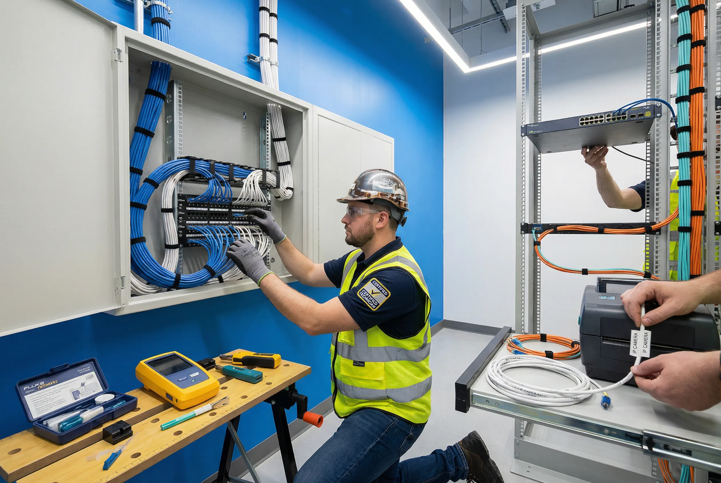
Figure 11.1: Professional installation in progress — zone cabinet setup with patch panel termination, Cat6A cable management with Velcro ties, fiber routing with bend radius guides, and cable labeling using a thermal label printer
Correct Installation Sequence
- Step 1 — Pathway preparation: Install cable trays, conduits, and J-hooks before pulling any cable. Verify separation from power runs and confirm tray fill is within limits.
- Step 2 — Cable pulling with tension control: Use a fish tape or pull string; never exceed manufacturer-specified maximum pull tension (typically 110 N for Cat6A). Avoid kinking or crushing.
- Step 3 — Service loops: Leave a minimum 300 mm service loop at both the camera end (inside junction box) and the patch panel end. This allows re-termination without pulling new cable.
- Step 4 — Termination at patch panel / keystone: Terminate using the correct T568B pinout, minimize untwist (≤13 mm for Cat6A), and use the correct punch-down tool with the correct blade setting.
- Step 5 — Label both ends immediately: Apply printed labels at both the camera/junction box end and the patch panel port before moving to the next cable. Never rely on memory or retroactive labeling.
- Step 6 — Patch to switch: Use the correct category patch cord (Cat6A for Cat6A permanent links). Route through horizontal cable managers; do not drape over equipment.
- Step 7 — Certify and test: Run 100% certification on all permanent links. Test fiber with OLTS and OTDR. Perform PoE load test at the far end of the longest run.
- Step 8 — Update as-built: Update cable schedule and drawings to reflect actual installed positions before proceeding to the next zone.
Common Installation Errors (9 Critical Mistakes)
| Error | Consequence | Correct Practice |
|---|---|---|
| Exposed outdoor RJ45 connectors | Water ingress → corrosion → intermittent fault | Use IP-rated junction box with sealed cable glands |
| Excessive pull force on cable | Pair deformation → certification failure → hidden faults | Use pull string with tension limiter; max 110 N for Cat6A |
| Sharp bends at corners and cabinet entries | Impedance increase → packet errors; fiber breakage | Use bend radius guides; minimum 32 mm for Cat6A, 30 mm for fiber patch |
| Mixed patch cord categories | Channel downgrade → inconsistent performance | Match patch cord category to permanent link category |
| No service loop at camera or panel | Cannot re-terminate without pulling new cable | Leave minimum 300 mm loop at both ends |
| Shielded cable without proper bonding | Shield acts as antenna → increased noise | Single-point bonding at patch panel end; verify continuity |
| Missing fire-stopping at penetrations | Compliance failure; fire spread hazard | Apply approved intumescent sealant; photograph before closing |
| Unlabeled cable ends | Extended MTTR; risk of wrong port operation | Print and apply labels at both ends before moving to next cable |
| Dirty fiber connectors before patching | High insertion loss → uplink instability | Clean every connector with IEC 61300-3-35 method; inspect with scope |
11.3 Workmanship Norms
Workmanship norms define the minimum physical quality standards that every installation must meet, regardless of the specific products or tools used. These norms are the basis for quality inspection during installation and for acceptance testing at handover. They address the seven most critical dimensions of cabling workmanship.
- Separation from power: Maintain minimum 150 mm separation from AC power cables in parallel runs. Cross at 90° only. Use metallic dividers in shared trays where separation cannot be maintained.
- Tray fill control: Do not exceed 40% fill ratio in cable trays to allow heat dissipation and future additions. Avoid crushing cables with over-filled trays or excessive tie tension.
- Strain relief at endpoints: Apply strain relief clamps or cable glands at both the camera mount and the cabinet entry. The cable jacket, not the conductors, must bear any mechanical stress.
- Grounding and bonding: Bond all cabinets, racks, and SPDs to the building earth busbar with short, direct conductors (≤1 m where possible). Use appropriate lug crimps and anti-corrosion compound for outdoor connections.
- Ventilation clearance: Maintain minimum 50 mm clearance above and below active equipment in cabinets. Do not route cables across switch air inlets or exhausts.
- Physical protection: Protect exposed cable runs in public or accessible areas with conduit, armor, or surface-mounted trunking. Secure conduit at maximum 1 m intervals.
- Thermal management: Do not co-locate high-heat equipment (UPS, high-density PoE switches) without adequate ventilation planning. Monitor cabinet temperature under full PoE load before handover.
11.4 Debugging Methods
Systematic debugging follows a structured isolation process: confirm the symptom, identify the layer (physical, data link, network, application), isolate to a specific component, apply the fix, and verify resolution. The following problem classes cover the most common fault scenarios encountered in IP surveillance cabling deployments. Each class includes isolation steps and resolution actions.
| Problem Class | Typical Symptoms | Isolation Steps | Resolution |
|---|---|---|---|
| Link Down | Camera offline; switch port shows down | Check physical port LEDs → swap patch cord → check certifier result → check switch port config | Replace faulty patch cord; re-terminate if certification fails; check switch port for damage |
| Intermittent Drops | Camera goes offline periodically; recording gaps | Check switch port error counters → inspect outdoor junction for moisture → check termination quality → check EMI sources nearby | Reseal outdoor junction; re-terminate; add EMI separation; replace CCA cable if found |
| PoE Issues | Camera reboots at night; PoE port cycling | Check switch PoE budget utilization → measure DC resistance of cable → verify camera max power class → check for long runs | Redistribute cameras to reduce per-switch load; upgrade to PoE++ if needed; replace undersized cable |
| High Latency / Jitter | PTZ control lag; VMS buffering | Check uplink utilization → verify QoS marking → check for broadcast storms → check switch CPU | Upgrade uplink speed; implement QoS; isolate broadcast domain; replace overloaded switch |
| Fiber Uplink Loss | Multiple cameras offline simultaneously; uplink port down | Clean fiber connectors → check DOM (digital optical monitoring) → run OTDR → check splice quality | Clean connectors with IEC method; re-splice if OTDR shows high-loss event; replace damaged fiber |
| Wrong Camera Feed / Mapping | VMS shows wrong camera at location; security gap | Trace physical cable from camera to patch panel port → compare against as-built → verify VMS IP assignment | Correct physical patching; update as-built; update VMS camera mapping; re-label affected ends |
11.5 Rack and Cabling Layout Highlights
The physical layout of the headend rack and zone cabinets has a direct impact on maintainability, thermal performance, and long-term reliability. A well-organized rack layout follows a consistent top-to-bottom hierarchy that separates fiber, copper, active equipment, and power infrastructure. The following principles define the recommended rack layout for surveillance headend and zone cabinets.
- Top of rack — Fiber ODF: Fiber ODF (optical distribution frame) at the top provides clean entry for backbone fiber, with bend radius guides and dust-capped spare adapters.
- Core / aggregation switch: Immediately below the ODF for short fiber patch cord runs. SFP+ uplinks connect directly to ODF without crossing other equipment.
- Patch panels: Below the core switch, with horizontal cable managers between each patch panel and the switch. One cable manager per 1U of patching is the minimum standard.
- Vertical cable managers: On both sides of the rack to route patch cords cleanly from panels to switches without crossing the equipment face.
- Power separation: AC power (PDU, UPS) on the left side of the rack; data cabling on the right. Never route AC cables through data cable managers.
- UPS at bottom: UPS at the bottom of the rack for low center of gravity and easy battery replacement access. PDU mounted vertically on the rack side.
- Blanking panels: All unused rack units must be filled with blanking panels to maintain airflow direction and prevent hot-air recirculation.