Chapter 7: Support & Integration
Supporting systems, power infrastructure, environmental monitoring, cable management, grounding, and third-party system integration requirements.
7.1 Integrated Supporting Equipment Overview
A surveillance cabling system does not operate in isolation — it depends on a comprehensive set of supporting equipment to ensure continuous operation, maintainability, and integration with other building systems. The diagram below illustrates all major supporting components integrated within a typical zone cabinet and the connections between them. Understanding these interdependencies at the design stage prevents costly omissions and ensures the system meets uptime and maintainability requirements.
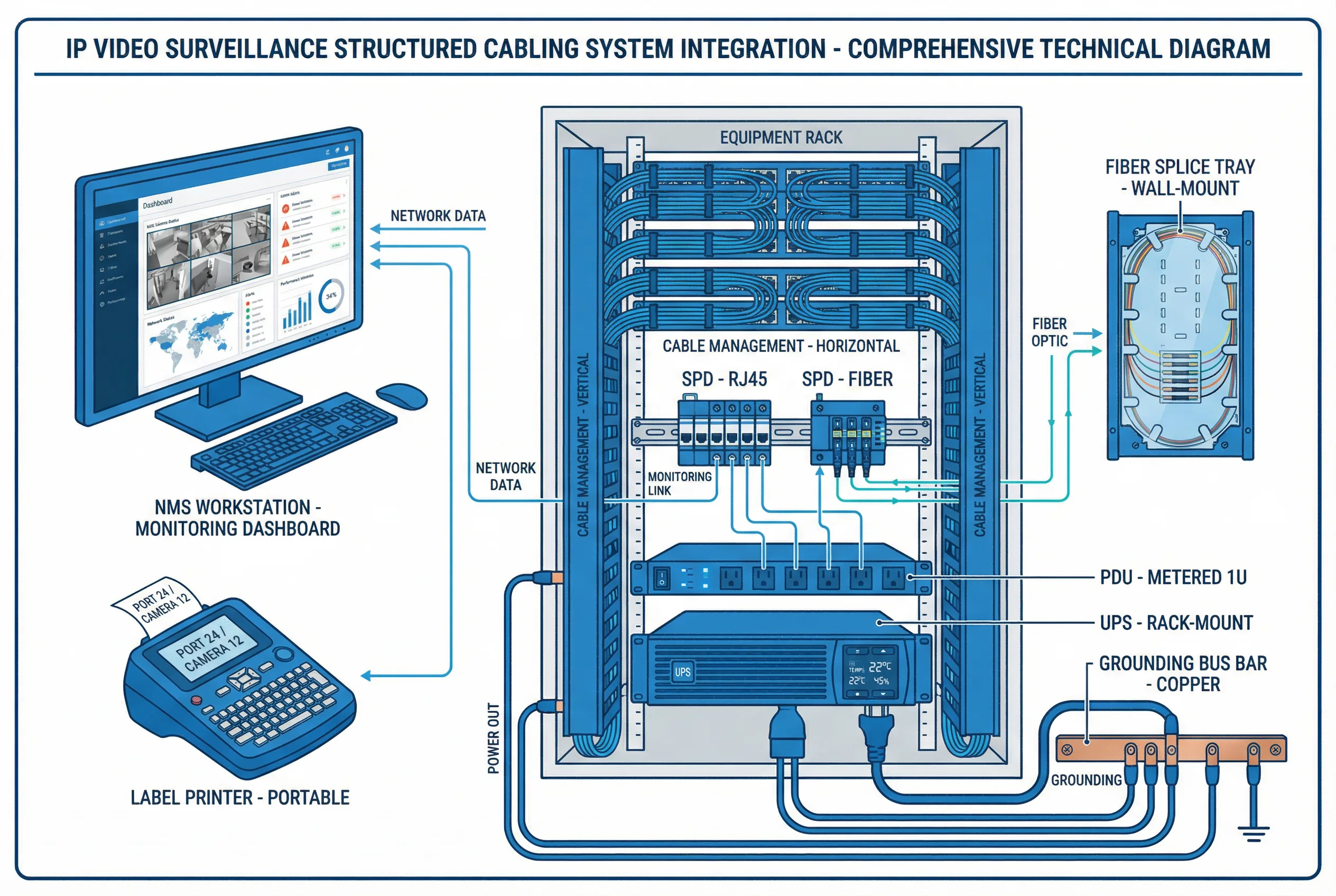
Figure 7.1: Integrated Supporting Equipment — All Components in a Single System View (UPS, PDU, SPD, Cable Management, Grounding, NMS, Environmental Monitoring, Fiber Splice Tray, Label Printer)
| Supporting Component | Function | Key Specification | Integration Point |
|---|---|---|---|
| UPS (Uninterruptible Power Supply) | Power continuity during outages | Min 30-min runtime at full load; rack-mount | Feeds PDU; monitored via SNMP |
| PDU (Power Distribution Unit) | Distributes AC power to all active equipment | Metered, with surge protection, 1U | Connected to UPS output |
| Surge Protection Device (SPD) | Protects against lightning and transient surges | IEC 61643-21; <1 ns response; DIN rail | Inline on all outdoor cable entries |
| Grounding Bus Bar | Equipotential bonding of all metallic parts | Copper, wall-mount; ≥6 mm² bonding conductors | Connected to building earth system |
| Horizontal Cable Manager | Routes and organizes patch cords | 1U with finger duct, both sides | Between patch panel and switch |
| Vertical Cable Manager | Routes cables along cabinet sides | Side-mount, with covers | Cabinet interior sides |
| Environmental Sensor | Monitors temperature and humidity in cabinet | ±0.5°C, ±3% RH; SNMP/Modbus output | Connected to NMS for alerting |
| Fiber Splice Tray | Protects and organizes fiber splices | Wall-mount; 12–24 splice capacity | At fiber entry points |
| Network Management System (NMS) | Centralized monitoring of all network devices | SNMP v2c/v3; syslog; dashboard alerts | Connects to all managed switches and UPS |
| Label Printer | Produces cable, port, and cabinet labels | Portable; prints on heat-shrink or self-lam labels | Used during installation and maintenance |
7.2 Power Infrastructure Requirements
Reliable power infrastructure is the foundation of surveillance system availability. The power design must account for the total PoE load of all cameras, the power consumption of active network equipment, and the runtime requirements of the UPS. A common design error is sizing the UPS based on normal operating load without accounting for the inrush current when all cameras restart simultaneously after a power event. A 20–30% margin above calculated peak load is recommended for UPS sizing.
| Parameter | Calculation Method | Recommended Margin |
|---|---|---|
| Total PoE load | Sum of all camera max PoE draw (use PoE++ for PTZ) | +20% for inrush and future cameras |
| Switch power consumption | From switch datasheet at full PoE load | +10% for temperature derating |
| UPS capacity | Total load × 1.3 (safety factor) | +30% above calculated peak |
| UPS runtime | Based on battery capacity and load | Minimum 30 min; 60 min recommended |
| PDU circuit rating | Total load / 0.8 (80% rule for continuous load) | Never exceed 80% of circuit breaker rating |
7.3 Integration with Building Management Systems (BMS)
Modern surveillance systems increasingly integrate with Building Management Systems (BMS) and other security subsystems to provide unified situational awareness. The cabling infrastructure must support these integrations by providing dedicated network paths, appropriate bandwidth allocation, and compatible interface standards. Common integrations include access control (for camera-door event correlation), fire alarm systems (for evacuation camera activation), and HVAC systems (for camera cabinet environmental control).
| Integration | Interface | Cabling Requirement | Bandwidth |
|---|---|---|---|
| Access Control System | TCP/IP, RS-485, Wiegand | Cat6A or dedicated RS-485 cable | Low (<1 Mbps) |
| Fire Alarm System | Dry contact relay, TCP/IP | Shielded twisted pair or Cat6A | Very low |
| BMS / SCADA | BACnet/IP, Modbus TCP | Dedicated VLAN on existing Cat6A | Low (<10 Mbps) |
| Video Analytics Server | TCP/IP (RTSP, ONVIF) | Dedicated VLAN, 1G minimum | Medium (depends on camera count) |
| VMS (Video Management Software) | TCP/IP, ONVIF Profile S/G | 10G uplink to server farm | High (full bitrate of all cameras) |
| Intercom / PA System | SIP, TCP/IP | Cat6A on surveillance VLAN or separate | Low (<1 Mbps) |
7.4 Cable Management Best Practices
Proper cable management is not merely aesthetic — it directly impacts system reliability, troubleshooting efficiency, and long-term maintainability. Poorly managed cables create airflow restrictions that cause equipment overheating, introduce physical stress on connectors that leads to intermittent failures, and make fault isolation extremely time-consuming. The following practices must be enforced throughout the installation process.
| Practice | Requirement | Rationale |
|---|---|---|
| Patch cord length | Use shortest appropriate length (0.5–3 m) | Reduces clutter and airflow restriction |
| Velcro straps | Use velcro only (no zip ties) on patch cords | Prevents crushing of cable pairs |
| Bend radius | Min 4× cable OD for Cat6A; 20× for fiber | Prevents performance degradation |
| Color coding | Assign colors by zone, function, or VLAN | Accelerates troubleshooting |
| Horizontal managers | 1U manager between every patch panel and switch | Keeps patch cords organized and accessible |
| Vertical managers | Side-mount vertical managers in all cabinets | Routes cables from top to bottom cleanly |
| Slack storage | Coil excess cable in dedicated slack loops | Allows future re-termination without re-pulling |