Chapter 12: Operations & Maintenance
O&M requirements, SLA tiers, daily monitoring strategy, preventive maintenance schedule, and a comprehensive troubleshooting guide for long-term system reliability.
12.1 O&M Requirements, Cycles, and SLA Tiers
A structured operations and maintenance program is essential to sustaining the reliability targets established at design time. The O&M program must define inspection cycles, spare parts inventory, change control procedures, access privilege management, and service level agreements (SLAs) that align with the criticality of each camera zone. Without a formal O&M program, even a well-installed system will degrade over time through accumulated small failures, documentation drift, and reactive-only maintenance.
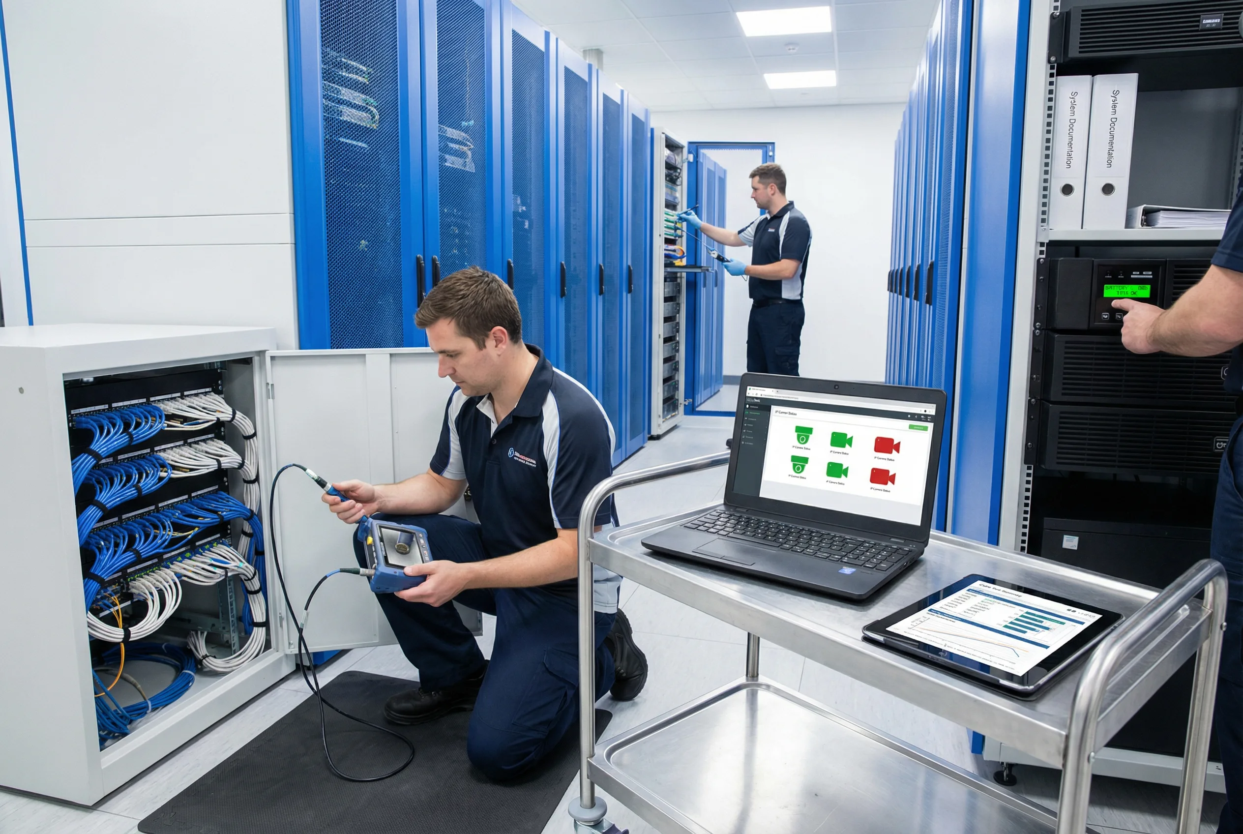
Figure 12.1: Preventive maintenance in progress — fiber inspection, network management dashboard review, cable test verification, and UPS battery status check in a well-organized surveillance equipment room
Inspection Cycles
- Weekly: Review NMS/VMS alarms; check PoE budget utilization trends; verify UPS battery status; review switch error counter logs.
- Monthly: Physical cabinet inspection — check for loose connections, cable damage, label legibility, and ventilation blockages. Verify SPD status indicators.
- Quarterly: Clean cabinet filters and vents; inspect outdoor seals and gaskets; re-tighten mounting screws and ground lugs; verify fiber dust caps on unused ports.
- Annual: Full system audit — random sampling re-certification of suspect links; UPS battery load test; complete as-built documentation review and update; security access review.
Spare Parts Inventory
- Fiber patch cords (LC-LC, LC-SC): minimum 10% of installed count per type
- Cat6A patch cords: minimum 10% of installed count per length
- SFP/SFP+ optics: minimum 2 units per type in use
- Surge protection cartridges: minimum 2 per type installed
- 1 spare PoE switch per tier (access and aggregation)
- Spare cameras for critical zones: minimum 2 units per camera model
- Keystone jacks and patch panel blanks: minimum 5% of installed count
SLA Tiers
| Priority Tier | Zone Examples | Response Time | Restore Time | Availability Target |
|---|---|---|---|---|
| P1 — Critical | Main entrance, perimeter, server room | 30 minutes | 4 hours | 99.9% monthly |
| P2 — Important | Internal corridors, parking, loading dock | 2 hours | 24 hours | 99.5% monthly |
| P3 — Non-critical | Storage areas, low-traffic zones | 1 business day | 3 business days | 99.0% monthly |
12.2 Daily Monitoring Strategy
Effective daily monitoring transforms the O&M function from reactive to proactive. By establishing baseline metrics and monitoring for deviations, the operations team can identify degrading conditions before they cause camera outages. The monitoring strategy covers four domains: power, thermal, link quality, and security. Alert grading ensures that the right personnel are notified at the right urgency level.
Key Monitoring Parameters
- PoE draw per port: Monitor actual PoE consumption per port; alert if any port exceeds 90% of its class limit or if total switch PoE budget exceeds 80%.
- Switch inlet temperature: Alert at 40°C warning, 50°C critical. Trend analysis can predict cooling failures before they cause reboots.
- Port error counters: Monitor CRC errors, input errors, and output drops. A rising CRC count on a specific port indicates a termination or cable quality issue.
- Port flap events: Any port that flaps more than 3 times in 24 hours should trigger a maintenance ticket. Flapping is a leading indicator of moisture ingress or termination failure.
- Uplink utilization: Monitor backbone uplink utilization; alert at 60% sustained (design threshold) and 80% peak.
- UPS alarms: Monitor battery health, bypass status, and input power quality. UPS battery replacement should be planned before end-of-life, not after failure.
Alert Grading and Escalation
| Alert Grade | Trigger Examples | Action | Escalation |
|---|---|---|---|
| Informational | Port utilization >50%; PoE draw >70% | Log and trend; no immediate action | None |
| Warning | Port flap ×1; temperature >40°C; PoE >80% | Schedule inspection within 48 hours | Team lead notification |
| Major | Port flap ×3 in 24h; temperature >45°C; uplink >80% | Dispatch technician within 4 hours | Operations manager notification |
| Critical | Camera offline (P1 zone); uplink down; UPS on battery | Immediate response per SLA tier | Full escalation chain; incident ticket opened |
12.3 Preventive Maintenance Schedule
Preventive maintenance is the most cost-effective way to sustain system reliability. The following twelve preventive maintenance tasks, organized by frequency, form the backbone of the annual maintenance plan. Each task should be documented with a completion date, technician name, and any findings or actions taken.
- Clean cabinet filters and vents (quarterly): Remove dust accumulation that restricts airflow and increases switch operating temperature.
- Re-tighten mounting screws and ground lugs (quarterly): Thermal cycling causes fasteners to loosen over time; loose ground connections increase impedance and safety risk.
- Inspect outdoor seals and gaskets (quarterly): UV degradation and temperature cycling cause seals to crack; replace any seal showing signs of hardening or cracking.
- Check SPD status indicators (monthly): Most SPD modules have a visual status indicator; a tripped or degraded module must be replaced before the next storm season.
- Review switch logs for CRC errors and flaps (weekly): Trending CRC errors identify degrading links before they cause outages.
- Random sampling re-certification (annual): Re-certify 10% of permanent links, prioritizing those in harsh environments or with a history of issues.
- Fiber cleaning before any re-patch (every event): Clean every fiber connector with IEC 61300-3-35 method before any re-patching operation, without exception.
- Verify label legibility and repair faded tags (quarterly): Labels in outdoor or high-UV environments fade within 1–2 years; replace with UV-resistant printed labels.
- UPS battery periodic test and replacement planning (annual): Perform a full-load battery discharge test annually; plan replacement before the battery reaches 80% of rated cycle life.
- Update as-built and port maps (every change): As-built documentation must be updated within 24 hours of any patching change; outdated documentation is a major MTTR driver.
- Validate night-time PoE loads seasonally: Camera IR heater loads increase in winter; validate that PoE budgets are not exceeded under cold-weather worst-case conditions.
- Check conduit integrity in public areas (semi-annual): Physical damage to conduits in accessible areas is a common cause of cable damage; inspect and repair promptly.
12.4 Troubleshooting and Repair Guide
The following symptom-to-fix table covers the ten most common fault scenarios encountered during the operational life of an IP surveillance cabling system. Each entry includes the most likely cause, a structured isolation process, the recommended fix, and a prevention strategy to reduce recurrence. This table should be included in the operations manual and made accessible to on-call technicians.
| Symptom | Likely Cause | Isolation Steps | Fix | Prevention |
|---|---|---|---|---|
| Camera reboots at night | PoE overload (IR heater + PTZ at night) | Check switch PoE logs for port cycling; measure actual draw at night | Redistribute cameras; upgrade to PoE++ switch; reduce per-port load | Include night-mode power in PoE budget design; apply 1.25× margin |
| CRC errors on specific port | Bad termination or EMI coupling | Swap patch cord; check certifier result; identify EMI sources near cable run | Re-terminate permanent link; add separation from power; replace CCA cable | 100% certification at installation; enforce separation rules |
| Camera drops after rain | Water ingress at outdoor junction | Inspect junction box for moisture; check cable gland integrity; check drip loop | Reseal junction with IP-rated box and sealed glands; add drip loop | Use IP66/IP67 junction boxes; inspect seals quarterly |
| Fiber uplink flapping | Dirty fiber connectors | Check DOM (Rx power); clean connectors; re-test with OLTS | Clean with IEC 61300-3-35 method; re-patch; if persistent, OTDR for physical damage | Clean before every patch; dust caps on all unused adapters |
| Wrong camera feed in VMS | Mislabeling or incorrect patching | Trace physical cable from camera to patch panel; compare to as-built; verify VMS IP | Correct physical patching; update as-built; re-label affected ends | Print-before-install labeling; as-built audit at acceptance |
| Multiple cameras offline simultaneously | Cabinet power failure (UPS or PDU) | Check UPS status; check PDU breaker; check switch power LED | Restore power; investigate root cause (overload, UPS battery, breaker trip) | UPS monitoring; breaker sizing with 20% margin; battery replacement plan |
| PTZ control lag | Uplink congestion or QoS misconfiguration | Check uplink utilization; verify QoS marking for control traffic; check switch CPU | Upgrade uplink; implement DSCP marking for PTZ control traffic; add QoS policy | Design uplink at ≤60% utilization; include QoS in switch template |
| Random camera offline (single camera) | Cabinet overheating → switch port throttling | Check switch inlet temperature; check cabinet ventilation; check PoE density | Add ventilation; reduce PoE density; relocate high-power cameras | Thermal design at installation; temperature monitoring with alerts |
| Camera not discovered by VMS | VLAN / ACL misconfiguration | Ping camera from VMS server; check VLAN assignment; review ACL rules | Correct VLAN assignment; update ACL to permit VMS-to-camera traffic | Use standardized switch configuration template; test at commissioning |
| Recording gaps in NVR/VMS | Storage full or disk failure | Check storage utilization; check disk health (SMART); check recording schedule | Expand storage; replace failed disk; adjust retention policy | Storage capacity alerts at 80%; annual storage capacity review |
Guide Complete
You have reached the end of the Video Surveillance Structured Cabling Design Guide. This guide has covered all twelve chapters from system components and design methodology through to installation, quality acceptance, and long-term operations and maintenance.