Chapter 10: Quality & Acceptance
Distinguishing good from poor installations, common defect risk chains, quality control practices, and the structured acceptance checklist matrix for IP surveillance cabling systems.
10.1 Quality Distinction: Good vs. Poor Installations
The visual and functional difference between a professionally executed cabling installation and a substandard one is immediately apparent to a trained eye. A high-quality installation is characterized by disciplined cable management, consistent labeling, proper termination technique, and proactive environmental protection. Poor installations, by contrast, exhibit shortcuts that may appear functional at commissioning but invariably generate recurring faults, extended MTTR, and costly remediation. The comparison below illustrates the most critical distinguishing factors that field engineers and acceptance inspectors should evaluate.
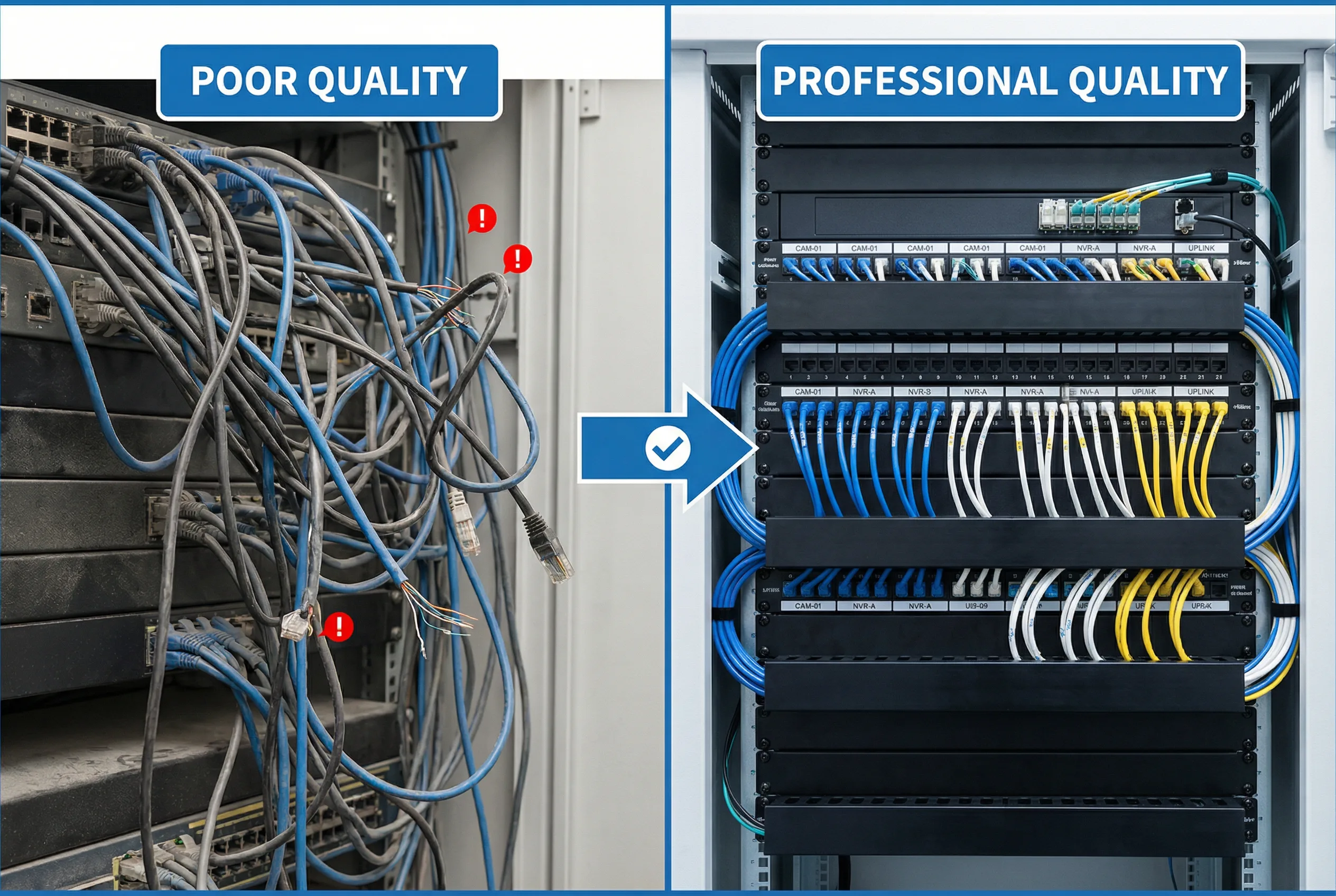
Figure 10.1: Side-by-side quality comparison — poor installation (left) vs. professional-grade installation (right) showing cable management, labeling, and termination discipline
Field Identification Tips (10 Key Checks)
The following ten field checks provide a rapid quality assessment that can be performed during walkthrough inspections, without requiring test equipment. Each check targets a failure mode that is statistically significant in IP surveillance cabling deployments.
- Labels at both ends: Every cable must be labeled at both the camera end and the patch panel port, readable without moving cables. Missing or illegible labels are the single largest contributor to extended MTTR.
- No over-tight zip ties: Cable jackets should not be deformed by fasteners. Velcro ties or hook-and-loop straps are preferred; over-tightened nylon zip ties increase impedance and can cause intermittent faults under temperature cycling.
- Bend radius respected: Cat6A minimum bend radius is 4× cable diameter (typically ≥32 mm); fiber minimum is 30 mm for patch cords and 10× diameter for installed fiber. Violations cause signal degradation and eventual physical failure.
- Outdoor terminations sealed: All outdoor RJ45 connections must be inside IP-rated junction boxes with sealed cable glands. Drip loops must be visible below every cable entry point to prevent water tracking into the box.
- Patch panels used: Permanent links must terminate on patch panels, not directly into switch ports. Direct termination prevents testing, increases switch port wear, and makes moves/adds/changes destructive.
- Fiber connectors clean: Fiber end-faces must be inspected and cleaned before every connection. Dust caps must be in place on all unused adapters. A single contaminated connector can cause uplink instability affecting dozens of cameras.
- Cabinets ventilated: No blanking panels missing, no vents blocked by cables, and no heat sources stacked. Switch inlet temperature should be verified under full PoE load.
- Grounding straps present and uncorroded: Cabinet-to-busbar bonding straps must be visible, properly torqued, and free of corrosion. Missing bonding is a safety and EMI hazard.
- Fire-stopping at penetrations: All cable penetrations through fire-rated walls, floors, and ceilings must be sealed with approved intumescent materials. This is a compliance requirement in virtually all jurisdictions.
- Port maps available and accurate: A laminated or digital port map must be present in or on each cabinet, accurately reflecting current patching. Outdated maps are as harmful as no maps.
10.2 Common Defects and Risk Chains
Installation defects rarely cause immediate catastrophic failure. Instead, they create latent risk chains that manifest as recurring faults under operational stress — temperature extremes, rain events, aging, or load increases. The table below maps the most common defects to their immediate symptoms, downstream risk chains, and recommended remediation actions. Understanding these chains is essential for root-cause analysis and for prioritizing remediation work.
| Defect | Immediate Issue | Risk Chain | Typical Fix |
|---|---|---|---|
| Poor termination (punch-down or crimp) | Packet errors / link flaps | Recording gaps → blind spots → incident evidence loss | Re-terminate and re-certify the link |
| CCA (copper-clad aluminum) cable used | Excessive DC resistance → voltage drop | Camera night reboot (IR heater load) → recurring tickets → shortened camera life | Replace with pure copper Cat6A |
| No sealing on outdoor junctions | Water ingress during rain | Corrosion → intermittent faults → full link failure → camera offline | Rework junction with IP-rated box and sealed glands |
| Dirty fiber connectors | High insertion loss | Uplink instability → multiple cameras drop simultaneously | Clean with IEC 61300-3-35 method, re-test with OLTS |
| Mislabeling or no labeling | Wrong port operated during incident | Long MTTR → additional cameras taken offline during repair | Relabel all ends, audit against as-built |
| Overheated cabinet | Switch thermal throttling or reboot | Multiple cameras offline simultaneously → security gap | Add ventilation, reduce PoE density, or relocate cabinet |
| No patch panel (direct to switch) | Cannot test or re-route without downtime | Any move/add/change requires cable pull → extended downtime | Retrofit patch panel; re-terminate permanent links |
| Missing SPD / surge protection | No protection during lightning event | Switch port damage → multiple cameras offline → costly replacement | Install SPD at all outdoor cable entries |
10.3 Quality Control Practices
Quality control in surveillance cabling is a continuous process spanning procurement, installation, testing, commissioning, and handover. The following ten practices represent the minimum quality management framework for a professional deployment. Each practice targets a specific failure mode and should be documented as part of the project quality plan.
- Incoming inspection: Verify cable markings, check vendor authenticity certificates, perform random cut-sample checks to confirm solid copper conductors and correct AWG.
- Tool calibration: Ensure punch-down tools, cable certifiers, and fiber test equipment are within calibration dates. Uncalibrated certifiers produce invalid test reports.
- Termination standards enforcement: Mandate T568B (or project-standard) pinout, minimum untwist at termination, and consistent keystone/patch panel brand within each zone.
- Cable routing separation: Enforce minimum 150 mm separation from power cables; cross at 90° only; document tray fill ratios to prevent over-fill.
- Print-before-install labeling: Labels must be printed and applied before cable is pulled, verified against the floor plan at the time of installation — not retroactively.
- 100% certification testing: Every permanent link must be certified to TIA-568-C.2 (Cat6A) or ISO/IEC 11801 Class EA standards. No sampling — 100% pass rate required for acceptance.
- Fiber loss testing: All fiber links tested with OLTS (insertion loss) and OTDR (reflectance, splice quality). Results archived as part of as-built documentation.
- As-built documentation updated daily: As-built drawings and cable schedules must be updated at the end of each working day. Photo records of concealed works (in-slab, in-wall) are mandatory before closing.
- 72-hour commissioning soak: After all cameras are connected, run a 72-hour continuous recording soak test. Review switch logs for any port flaps, errors, or PoE events.
- Change control post-handover: All patching changes after handover must be logged via a change ticket. A patch log (date, who, what) must be maintained in each cabinet.
10.4 Acceptance Standards and Test Items
The acceptance process is the formal gate between installation completion and system handover to the operations team. It must be structured, evidence-based, and witnessed by the client representative. The matrix below defines the minimum acceptance test items, methods, pass criteria, and required evidence for each category. All items must pass before a certificate of completion is issued.
| Category | Test Item | Method | Pass Criteria | Evidence Required |
|---|---|---|---|---|
| Function | Live view — all cameras | VMS client review | 100% of cameras stream without error | Screenshots with timestamps |
| Performance | Bitrate within profile | VMS / NMS traffic stats | Actual bitrate within ±10% of design profile | Traffic reports exported |
| Stability | 72-hour soak test | Switch logs + VMS recording review | Zero repeated port flaps; recording continuity ≥99.9% | Switch log export; VMS recording report |
| Reliability | Uplink failover test | Manually unplug uplink A; measure recovery | All cameras recover within defined SLA (e.g., <30 s) | Witnessed test report with timestamps |
| Security | VLAN / ACL audit | Switch config export + ping test | Camera VLAN isolated; no cross-VLAN access without ACL permit | Config export + test results |
| Electrical | PoE load measurement | Switch PoE status CLI + clamp meter | No switch exceeds 80% of rated PoE budget | Measurement sheet signed |
| Copper cabling | Link certification | Cable certifier (Fluke DSX / Versiv) | 100% PASS to Cat6A / Class EA standard | Certifier report PDF (all links) |
| Fiber | Insertion loss (OLTS) | Light source + power meter | Within link loss budget (typically ≤2–3 dB per link) | OLTS test report |
| Fiber | OTDR trace | OTDR (both directions) | No events exceeding 0.5 dB; no reflections > −45 dB | OTDR trace files archived |
| Grounding | Ground continuity | Low-resistance ohmmeter | Cabinet-to-earth resistance ≤1 Ω | Measurement sheet signed |
| Documentation | As-built accuracy audit | Random sampling trace test (10% of links) | As-built matches physical ≥99% of sampled links | Audit sign-off sheet |