Chapter 4: Architecture Design
Hierarchical network topology, zone cabinet design, and backbone planning for IP surveillance structured cabling systems.
4.1 Three-Tier Hierarchical Architecture
The standard architecture for IP surveillance structured cabling follows a three-tier model: Core/Headend, Distribution/Aggregation, and Access. This hierarchy mirrors enterprise network design principles and provides clear boundaries for fault isolation, capacity planning, and future expansion. Each tier has defined roles, performance requirements, and physical boundaries that guide both design and troubleshooting.
The Core tier houses NVR/storage servers, core switches with 10G uplinks, and centralized management systems in a dedicated equipment room. The Distribution tier aggregates traffic from multiple Access zones via fiber trunks, providing redundancy and bandwidth concentration. The Access tier delivers PoE power and Gigabit connectivity to individual cameras through Cat6A horizontal runs within each zone.
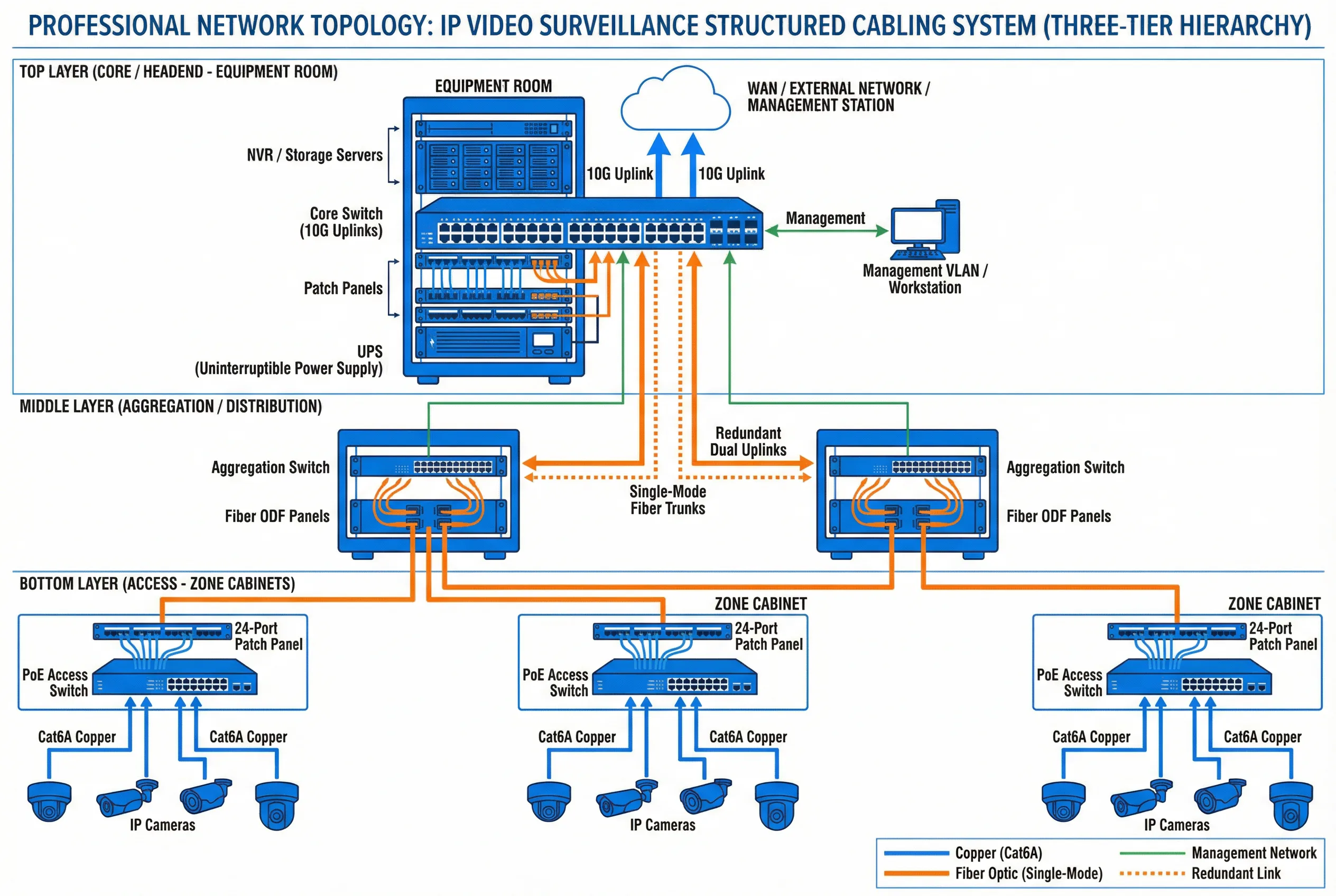
Figure 4.1: Three-Tier Hierarchical Topology for IP Video Surveillance Structured Cabling
| Tier | Role | Key Equipment | Uplink Speed | Redundancy |
|---|---|---|---|---|
| Core / Headend | Central management, storage, NVR | Core switch, NVR, storage, UPS | 10G / 40G | Dual power, LACP |
| Distribution / Aggregation | Zone aggregation, fiber termination | Aggregation switch, ODF, fiber patch panel | 1G / 10G fiber | Dual uplinks, STP/RSTP |
| Access | Camera connectivity, PoE delivery | PoE+ switch, Cat6A patch panel, zone cabinet | 1G copper | Optional redundant uplink |
4.2 Zone Cabinet Design and Equipment Layout
Each zone cabinet serves as the physical termination point for all horizontal camera runs within its coverage area. Proper cabinet design ensures cable management, thermal control, and maintainability. The standard zone cabinet layout follows a top-down sequence: fiber ODF, copper patch panel, cable manager, PoE switch, PDU, and UPS. This sequence minimizes cable crossing and provides logical separation between passive and active components.
Cabinet sizing must account for current equipment, spare capacity (typically 25–30%), and cable bend radius requirements. Thermal management is critical — PoE switches generate significant heat, and cabinets in non-air-conditioned spaces require ventilation fans or thermostatically controlled cooling. All cabinets must be grounded to the building earth system.
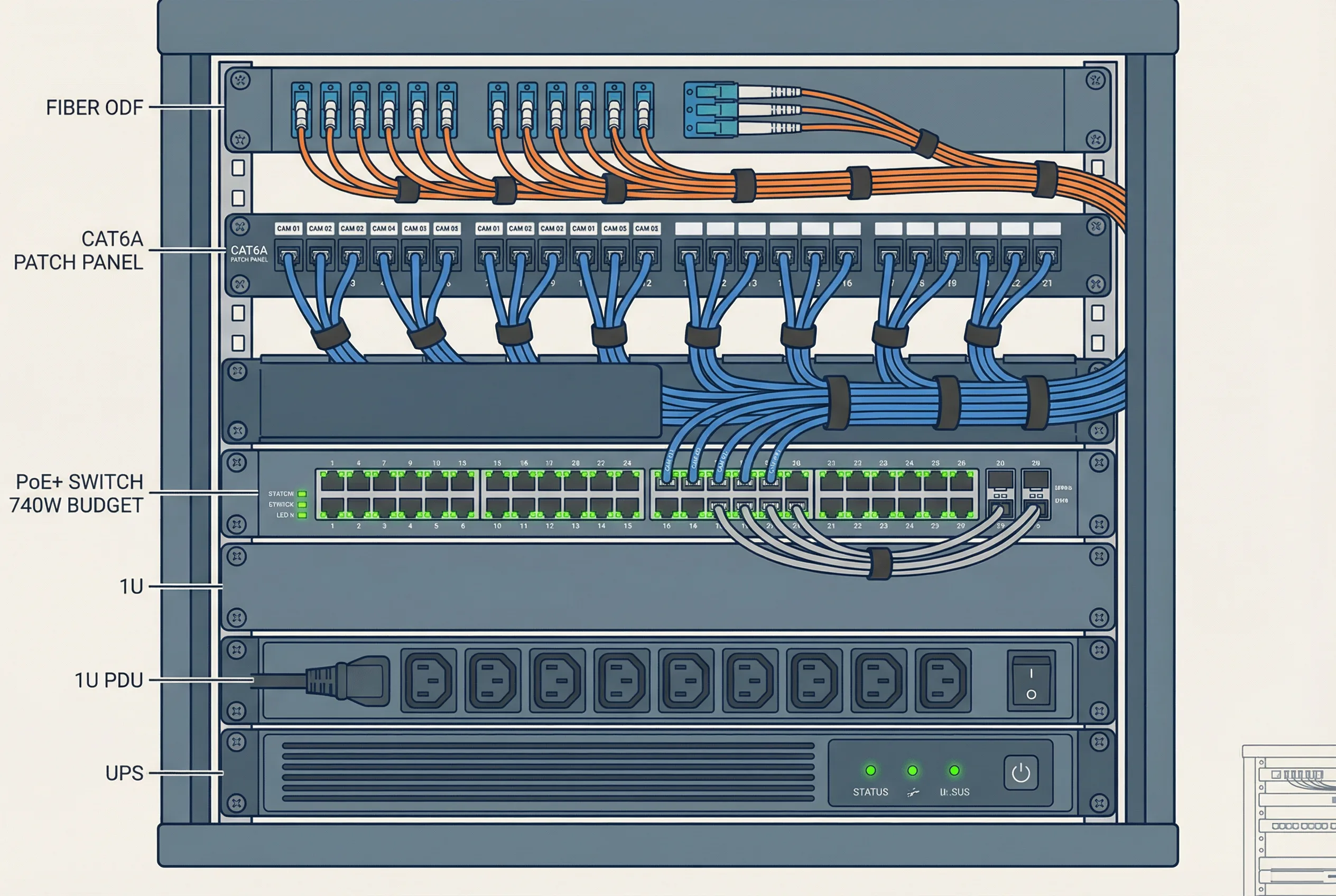
Figure 4.2: Typical Zone Cabinet Equipment Layout and Wiring Diagram
| Component | Position | Specification | Notes |
|---|---|---|---|
| Fiber ODF | Top (1U) | LC/SC adapters, 12–24 ports | Uplink fiber termination |
| Cat6A Patch Panel | 2nd (1U) | 24-port, T568B, labeled | Camera horizontal runs |
| Horizontal Cable Manager | 3rd (1U) | With finger duct, both sides | Patch cord routing |
| PoE+ Switch | Middle (2U) | 24/48 port, ≥370W / ≥740W | Camera power and data |
| Blank Panel | Filler | 1U blanks for unused space | Airflow management |
| PDU | Lower (1U) | Metered, with surge protection | Power distribution |
| UPS | Bottom (2U) | Min 30-min runtime at full load | Power continuity |
4.3 Backbone Planning and Fiber Routing
Backbone cabling connects zone cabinets to the distribution layer and ultimately to the core equipment room. For most enterprise deployments, single-mode fiber (OS2) is the preferred backbone medium due to its unlimited distance capability, immunity to EMI, and future-proof bandwidth. Multimode fiber (OM3/OM4) is acceptable for intra-building runs under 300 m where cost is a primary concern.
Backbone routes should follow dedicated cable trays or conduits separate from horizontal runs. Spare capacity of at least 25–50% additional fiber cores must be provisioned in each backbone run to support future expansion without re-pulling. All fiber splices and terminations must be documented with OTDR test results, and insertion loss must not exceed 3 dB end-to-end for any backbone link.
| Parameter | Single-Mode (OS2) | Multimode (OM4) | Cat6A Copper |
|---|---|---|---|
| Max distance | Unlimited (10+ km) | 400 m at 10G | 100 m at 10G |
| Bandwidth | Unlimited | 4700 MHz·km | 500 MHz (100 m) |
| EMI immunity | Complete | Complete | Partial (shielded) |
| Lightning isolation | Yes | Yes | No |
| Typical use | Inter-building, long runs | Intra-building <300 m | Horizontal drops ≤90 m |
| Max insertion loss | <3 dB end-to-end | <3 dB end-to-end | Per TIA-568 channel |
4.4 VLAN Segmentation and Network Architecture
Surveillance traffic must be isolated from general office or IT networks using dedicated VLANs. This isolation prevents surveillance bandwidth from competing with business-critical applications and reduces the attack surface for cybersecurity threats. A minimum of three VLANs is recommended: one for camera data, one for management access, and one for NVR/storage systems.
QoS (Quality of Service) policies should prioritize surveillance video traffic to prevent packet loss during network congestion events. Bandwidth reservation for surveillance should be calculated based on the total camera bitrate plus a 30–50% overhead margin for motion-triggered spikes, management traffic, and future expansion.
| VLAN | Purpose | Devices | Bandwidth Allocation |
|---|---|---|---|
| VLAN 10 (Camera) | Video data transport | IP cameras, encoders | ≥70% of uplink |
| VLAN 20 (Management) | Device management, NMS | Switches, NVR management ports | ≤10% of uplink |
| VLAN 30 (Storage) | NVR-to-storage traffic | NVR servers, SAN/NAS storage | ≥20% of uplink |
| VLAN 99 (Native) | Untagged / default isolation | No active devices | Blocked |