Chapter 2: Design Methods
Engineering principles, failure analysis, decision logic, and design dimensions for video surveillance cabling systems.
2.1 Core Design Principles
Effective video surveillance cabling design is grounded in a set of engineering principles that have been validated across thousands of deployments. These principles are not merely guidelines — they represent the accumulated lessons from recurring failure patterns and the engineering controls that prevent them. Each principle is conditioned on specific deployment scenarios and backed by established references.
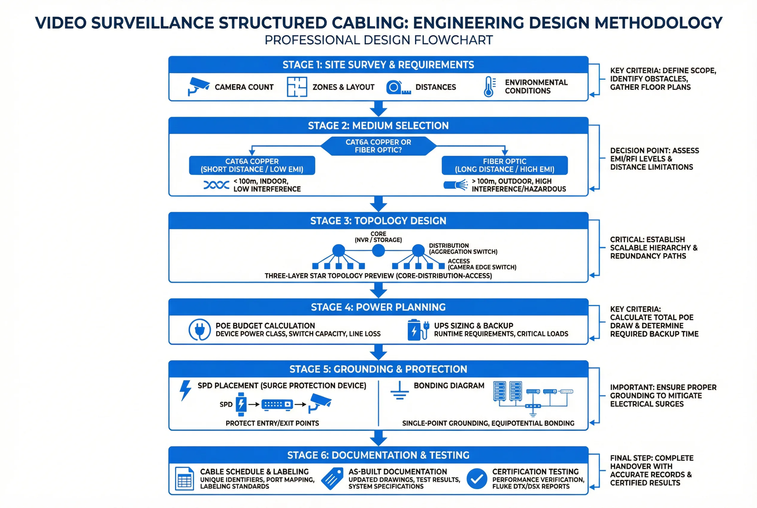
Figure 2.1: Engineering Design Methodology — Six-stage design process from site survey through documentation and testing acceptance.
| Design Principle | Condition / When Applicable | Engineering Reference |
|---|---|---|
| Use structured cabling with patch panels — never direct-to-switch permanent cables | All deployments with cabinets | Structured cabling methodology, maintainability |
| Keep copper short, use fiber for distance and outdoor aggregation | Channels >90 m or high EMI zones | Ethernet channel constraints + EMI immunity |
| PoE budget must include worst-case (night IR, heaters, PTZ motors) | Outdoor IR/PTZ/thermal cameras | Vendor max power + thermal derating specs |
| Every permanent link must be testable and traceable | All deployments | Structured cabling methodology |
| Pathway separation is a design control, not a construction detail | Co-existing power, VFD motors, elevators | EMC practices and separation standards |
| Use IP-rated enclosures and drip loops for outdoor terminations | Outdoor/parking/perimeter | Ingress protection practice (IP66/67) |
| Redundancy where repair time is unacceptable | Critical perimeters, public safety zones | Availability targets and MTTR analysis |
| Standardize labeling and numbering across civil, network, and VMS | Multi-team operations | Configuration management best practices |
| Design margins: thermal, power, bandwidth, space | Growth expected over 3–5 years | Capacity planning methodology |
| Grounding and surge protection are mandatory interfaces | Outdoor and long runs | Lightning/surge risk mitigation standards |
2.2 Failure Causes and Recommendations
Understanding the most common failure mechanisms is essential for designing preventive controls into the cabling system from the outset. The following table maps each failure cause to its mechanism, typical symptoms, prevention strategy, and verification method. These patterns represent the most frequently encountered issues across enterprise and campus surveillance deployments.
| Failure Cause | Mechanism | Typical Symptoms | Prevention | Verification |
|---|---|---|---|---|
| Bad terminations | High return loss/NEXT | CRC errors, port flaps | Certified installers + correct punch-down tools | Cable certification PASS report |
| Wrong cable type outdoors | UV/water degradation | Seasonal failures, cracking | Outdoor-rated jacket (PE), sealed ends | Visual inspection + spec check |
| Overfilled conduits | Heat + cable crush | Random drops, intermittent | Fill ratio control ≤40% | Pathway audit during installation |
| EMI coupling | Induced noise on copper | Packet loss spikes near motors | Separation, shielding, fiber in EMI zones | Error counter trend monitoring |
| PoE oversubscription | Voltage sag at far end | Night reboot cycles | Budget + 20–40% headroom | Load test at peak power conditions |
| Poor labeling | Human error during ops | Wrong camera mapping, slow MTTR | Labeling standards + print-before-install | Documentation audit sampling |
| Dirty fiber connectors | Increased insertion loss | Uplink instability, CRC errors | Mandatory cleaning procedure before patch | OLTS measurement + DOM monitoring |
| No surge/ground bonding | Equipment damage from transients | Post-storm port failures | SPDs + equipotential bonding | Continuity test + installation checklist |
2.3 Core Decision Logic
The design decision process follows a structured sequence that translates site requirements into specific engineering choices. Starting from camera count and bitrate policy, each decision step narrows the solution space based on measurable criteria. This prevents ad-hoc decisions that lead to inconsistent deployments across zones or sites.
- Define camera types and worst-case power/bitrate: Identify all camera models, their maximum PoE draw (including IR, heaters, PTZ), and their peak bitrate under motion conditions.
- Cluster cameras into zones and estimate distances to cabinets: Group cameras by physical proximity and measure or estimate the longest cable run in each zone. Runs approaching 90 m trigger fiber consideration.
- Choose access cabinet locations based on power availability, physical security, maintenance accessibility, and thermal environment.
- Select copper/fiber mix based on distance limits, EMI risk, lightning exposure, and budget. Outdoor runs longer than 30 m should default to fiber uplinks.
- Calculate bandwidth, PoE, UPS runtime, and fiber core counts using the formulas in Chapter 9 calculators, applying appropriate safety margins.
- Design pathways, separation, and grounding/SPD points — treat pathway routing as a primary design deliverable, not a construction afterthought.
- Finalize labeling, testing, and acceptance plan before installation begins, so test equipment and documentation templates are ready.
- Produce BOM and as-built requirements with revision control from day one of the project.
2.4 Key Design Dimensions Checklist
A complete design must address all seven dimensions listed below. Omitting any dimension creates a predictable failure mode that will surface during commissioning or operations. Use this checklist as a design review gate before finalizing any cabling design.
| Dimension | Key Questions | Typical Acceptance Evidence |
|---|---|---|
| Performance / Experience | Is latency, jitter, and frame integrity within spec? | Throughput test, error counter baseline |
| Stability / Reliability | Are link margin, power margin, and redundancy adequate? | 72h soak test, failover test |
| Maintainability | Can any port be traced, patched, and repaired quickly? | Traceability audit, MTTR measurement |
| Compatibility / Expansion | Are interfaces standards-based with spare capacity? | Capacity check, spare fiber/port count |
| Lifecycle Cost (LCC) | Is install cost vs. truck rolls vs. downtime optimized? | LCC analysis, fault frequency tracking |
| Energy / Environment | Are PoE efficiency, UPS losses, and ventilation adequate? | Power audit, thermal logging |
| Compliance / Certification | Are fire-stopping, low-voltage safety, and IP ratings met? | Compliance checklist, certification reports |